

Switch loads or enable signals without putting them on the controller I/O
Three optocoupler-input relay channels give a CNC controller, microcontroller or automation project clean low-voltage control of dry NO / COM / NC contacts.

One board, three independent contact outputs
Optocoupler inputs
S1, S2 and S3 accept 3.3 V or 5 V control logic. The low-voltage input stage separates controller-side signals from the switched contacts.
Dry changeover contacts
Each relay provides physical NC, COM and NO terminals, useful for load switching or for a servo-drive enable input that expects a contact closure.
Per-channel trigger choice
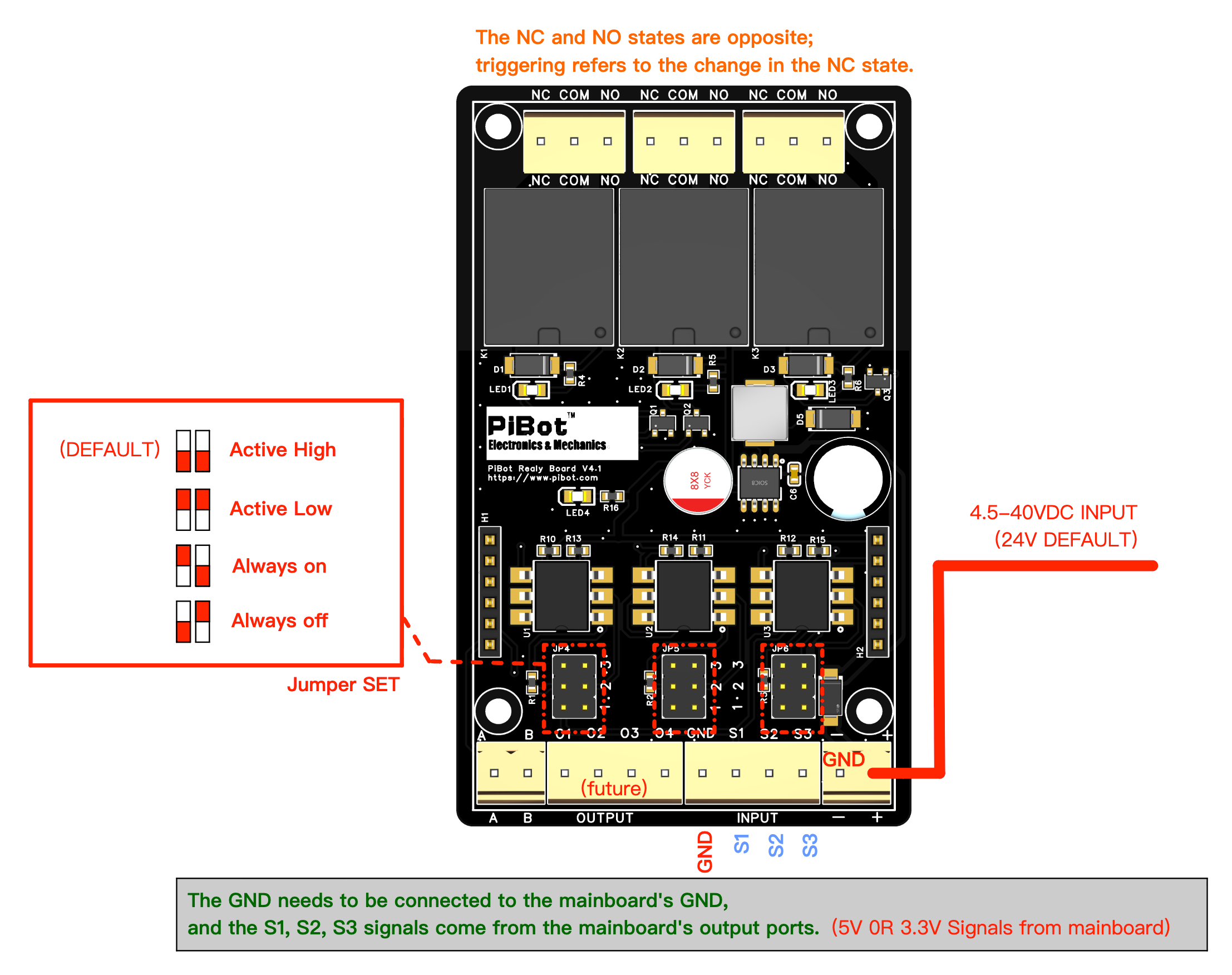
JP4, JP5 and JP6 independently select Active High, Active Low, Always on or Always off for K1, K2 and K3.
Understand the terminals and jumpers
Controller side
- Power: − / +, 4.5–40 V DC; 24 V is the documented default.
- Inputs: GND / S1 / S2 / S3.
- Logic: 3.3 V or 5 V signal.
- O1–O4: marked “future”; not used in the documented setup.
Switched side
- NO: open while the coil is released.
- COM: common contact.
- NC: closed while the coil is released.
Changing Active High to Active Low reverses which input level energises the coil; it does not rename the physical NO and NC terminals. Choose the contact and trigger polarity together for a safe boot, reset, alarm and power-loss state.
Documented with four PiBot FluidNC controllers
The orange boxes in each drawing are alternative signal sources. Select one route for S1/S2/S3—not all routes at once—and always include the shared GND.
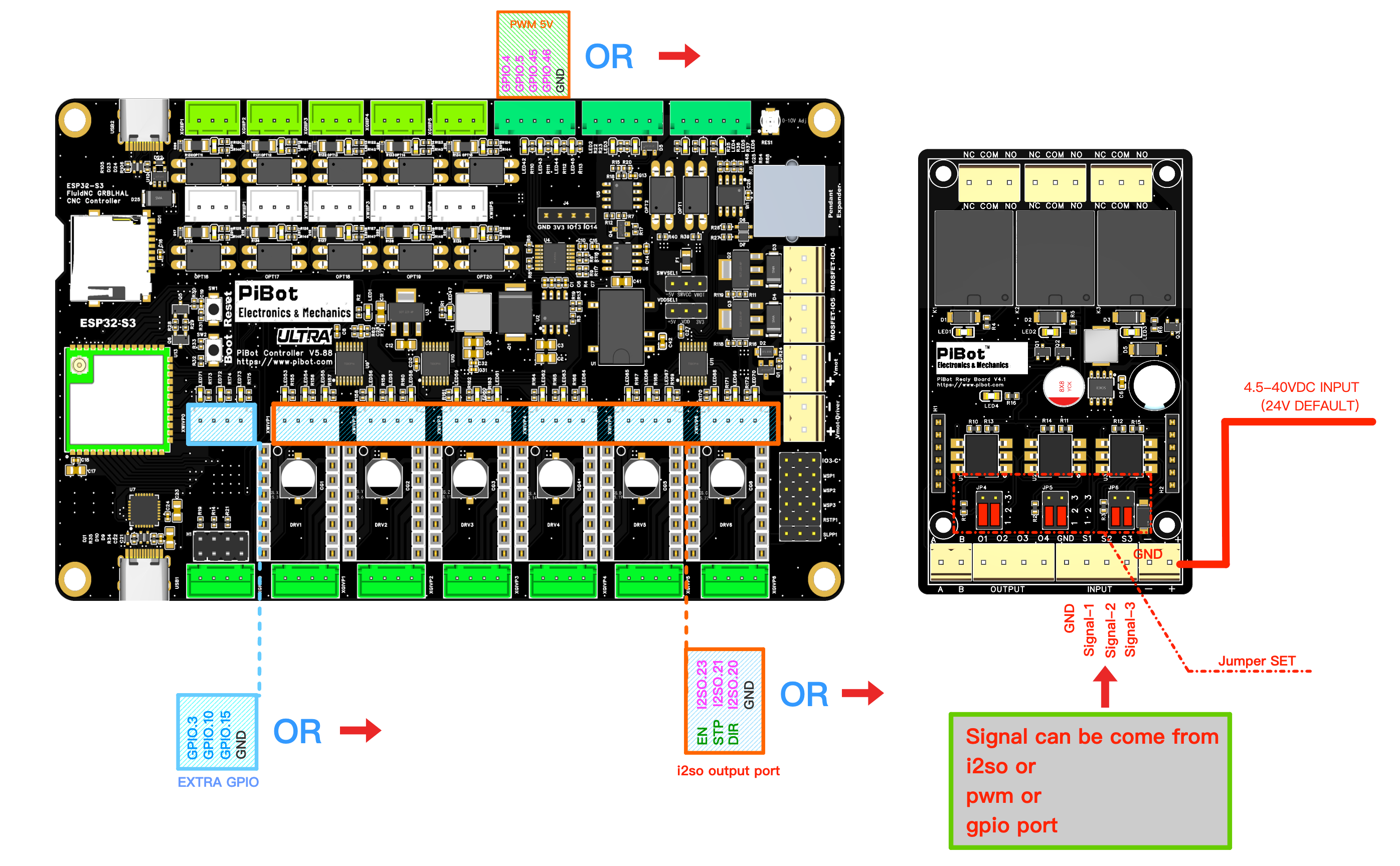
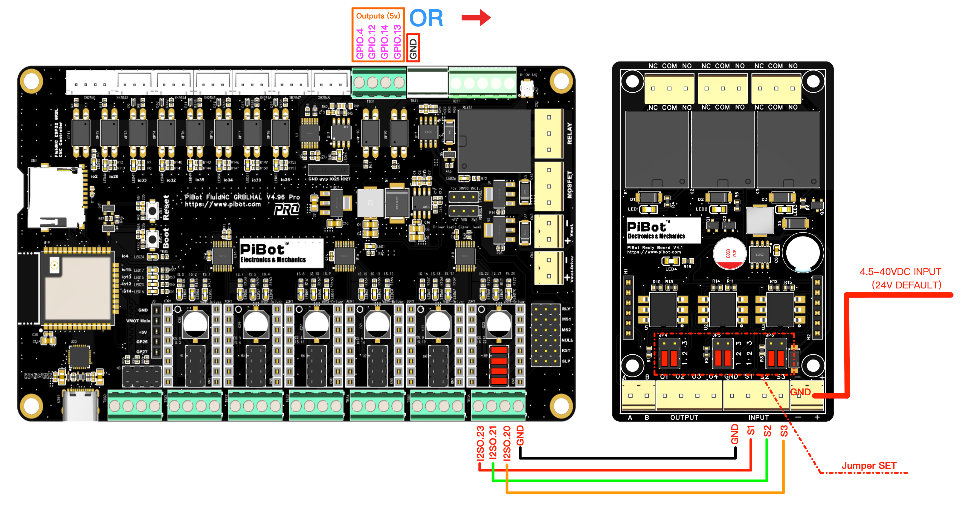
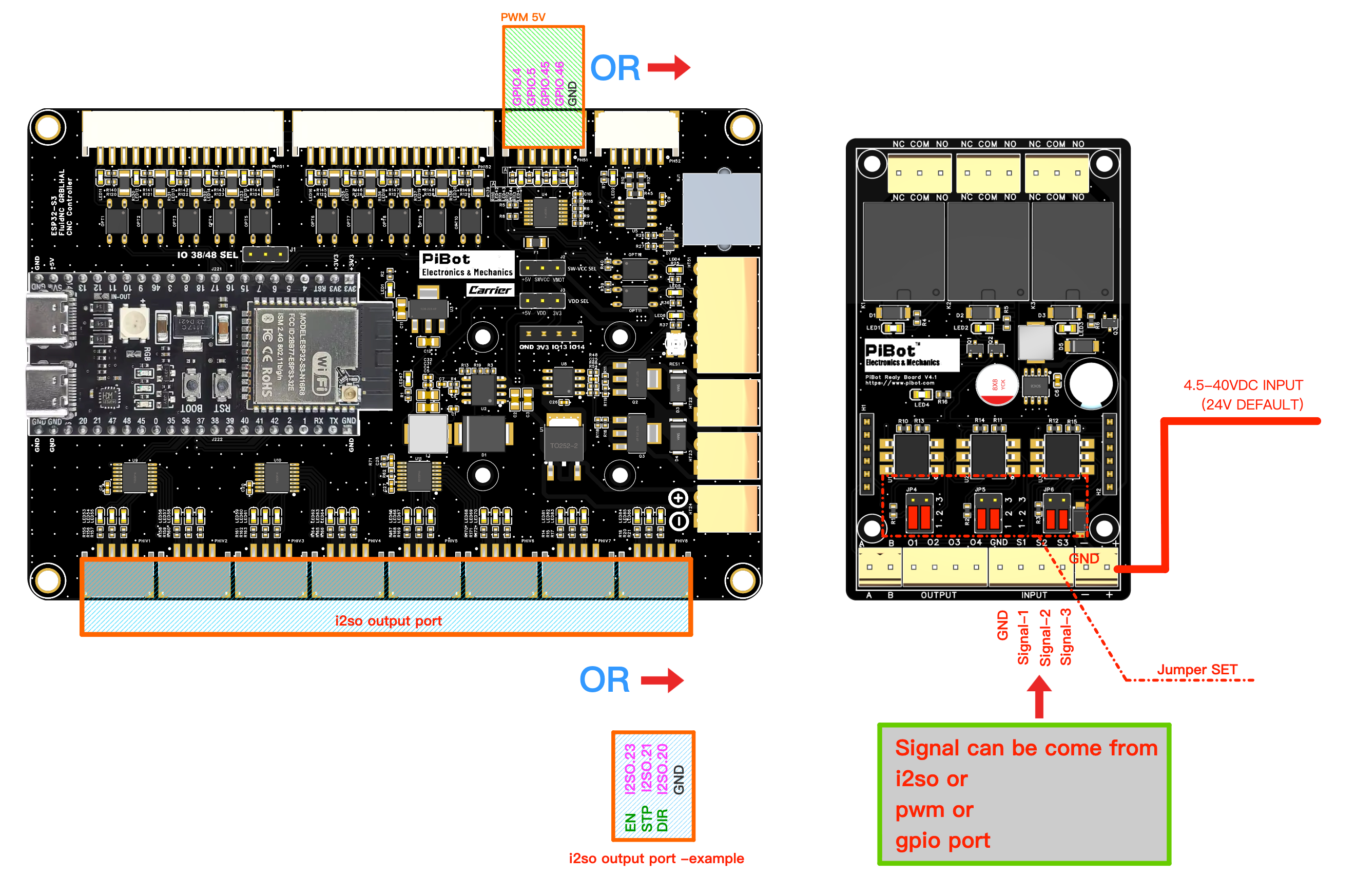
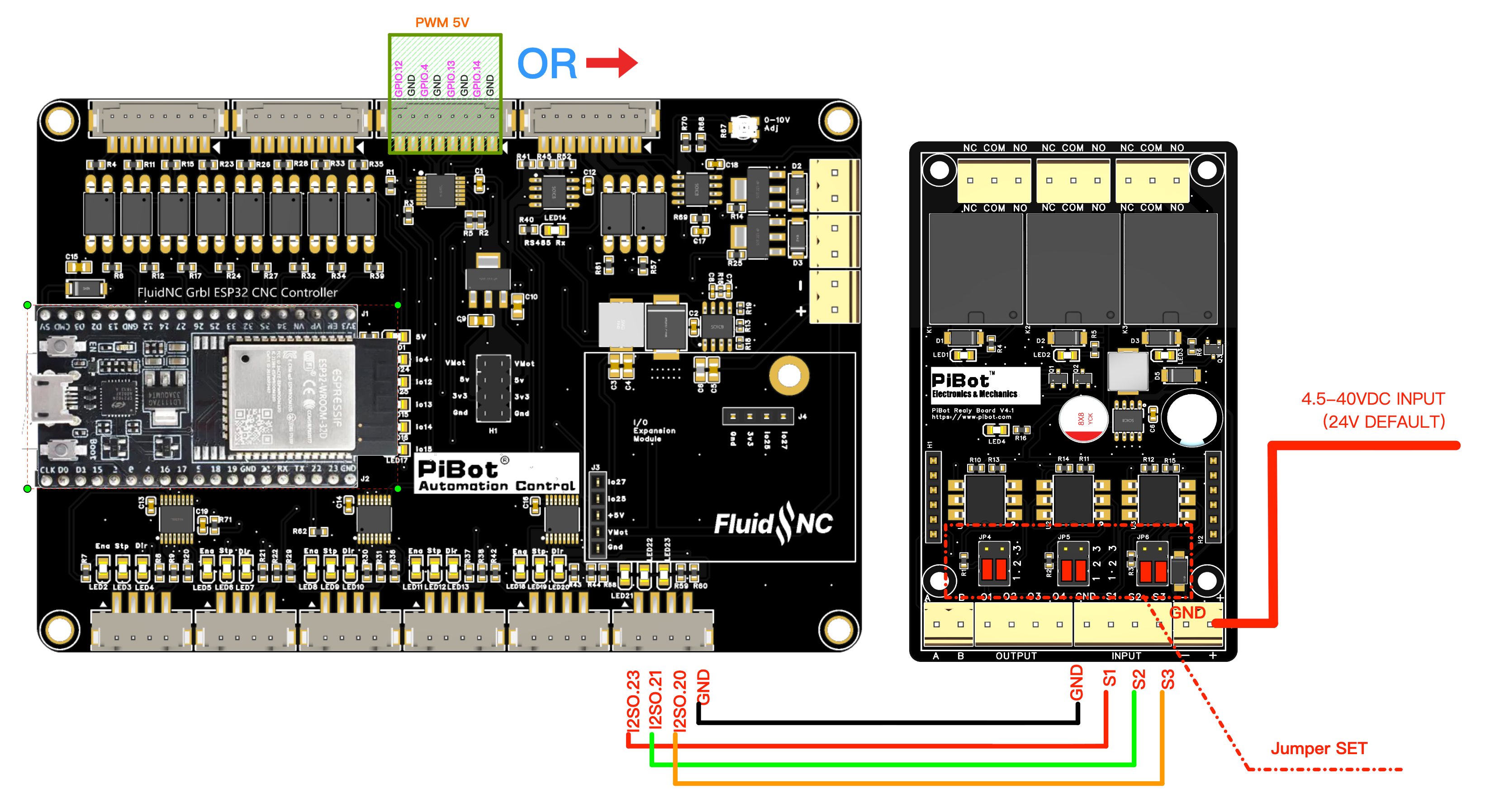
Four-step first test
Disconnect controller power, USB and relay-board power before changing wires or jumpers.
Set JP4/JP5/JP6, then choose NO or NC for the behaviour required at idle and during power loss.
Connect one selected signal route plus GND to S1/S2/S3, and power the board separately at − / +.
Verify one relay at a time, then meter COM–NO and COM–NC before connecting the real circuit.
FluidNC example
coolant:
  mist_pin: I2SO.23   # S1 · M7 on
  flood_pin: I2SO.21  # S2 · M8 on
  delay_ms: 0

user_outputs:
  digital0_pin: I2SO.20  # S3
# M64 P0 on · M65 P0 off
Expected result
M7operates only K1 / S1.M8operates only K2 / S2.M9releases K1 and K2.M64 P0/M65 P0operate and release K3 / S3.
This is a worked I2SO example, not a universal machine configuration. The exact available pins and shared-function restrictions depend on the controller; use its linked 4.3 guide.
Specifications
| Channels | 3 independent relays; NC / COM / NO dry contacts per channel |
|---|---|
| Input logic | 3.3 V or 5 V signal through optocoupler inputs |
| Board power | 4.5–40 V DC; 24 V documented default |
| Relay | SRD-05VDC-SL-C |
| Printed contact rating | 10 A at 250/125 VAC or 10 A at 30/28 VDC; the safe usable rating depends on load type, inrush, switching frequency, protection, enclosure and wiring |
| Optocoupler | 4N35 |
| Board dimensions | 85 × 50 × 20 mm |
| Mounting | 3 mm holes; 61 × 43 mm mounting pattern |
| Included | PiBot IsoSwitch V4 × 1 |
Documentation before wiring
Use the controller-specific guide
The complete Wiki reference covers all four jumper modes, controller pin choices, shared-function warnings, YAML, Pass/Fail checks and troubleshooting.
-250x250.jpg "DRV8825 Stepper Motor Driver")




%20(1)-250x250h.png "IPEX to SMA external antenna")
-250x250w.png "IPEX to SMA external antenna")