What is it
This controller is designed to operate a wide range of CNC machines. It can drive six motors and supports various spindles and lasers—including those with PWM, 485, and 0-10V outputs — compatibility with FluidNC, GRBLHAL, and GRBL1.1f.
Firmware Features
1. For the FluidNC official original firmware, It adopts the pin configuration of FluidNC 6x to ensure enhanced compatibility,FluidNC is very easy to configure. You never have to compile any software. All configuration, upgrading, etc can be done via web browser. we provide yaml example configuration file.
2. For grblHAL and GRBL1.1f, you can configure them directly via the WebBuild platform on grblHAL's official website. This ESP32 flash tool also allows for easy firmware uploading. Moreover, thanks to grblHAL's built-in compatibility mode for GRBL1.1f, you can utilize a wide range of software that requires GRBL1.1f support.
3. You can find relevant information on the official FluidNC and GRBLHAL wiki sites. In parallel, we are optimizing our Simple Tutorial with clear visuals and videos to streamline the learning process.
4. Compatible Software vs. Firmware, This table is based on our tests in October 2025. Be aware that software changes might have occurred or there might be some inaccuracies, so you can run your own tests.
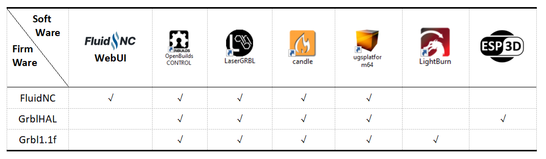
Additionally, some software like Estlcam and Easel have specific hardware requirements. You can use our corresponding control boards, which are designed to meet these requirements.
FluidNC Resources
Compatible with the FluidNC official original firmware, we provide yaml example configuration file.
- FluidNC Wiki
- Complete Download Package
- XYZABC Factory Test Config
- XYYZ Coolant Config
- TMC2130 Config (V49P-B only)
- TMC5160 Config (V49P-B only)
- Latest Firmware: GitHub Releases
GRBLHAL Resources
Compatible with the GRBLHAL official Web-builder, GRBLHAL can set to GRBL1.1f level.
The PIBot V4 board natively supports the GRBLHAL OLED, as this code was contributed by Luc from France (ESP3D Developer) and tested using the PiBot V4 mainboard.
- grblHAL web - GitHub Repository
- PiBot V4 Web Build - Web Builder
- PiBot V4 GRBLHAL Pinmap - Pinmap File
- Quick Start Guide - PiBot V4 GRBLHAL Quick Start
The 2025 Latest Version is V4.9 Plus B Now in Stock!
2024 V4.9P upgrade to 2025 V4.9PB,
Compared to the V4.9P version from 2024, V4.9PB have incorporated a voltage level selection function, allowing users to choose either 3.3V or 5V as the onboard drivers control voltage.
We have fixed some pin setting errors in V4.9P, and as a result, it can now support TMC2130 and TMC5160 drivers. (the old 2024 version V4.9P can not support TMC drivers)
How to Identify New Version
A:The versions shipped in 2025 are all the new ones, which are silkscreened with "PiBot FluidNC V4.9 PLUS B".
B:Below the relay on the PCB, there is a 3-pin jumper cap labeled "Driver Logic Signal Level".
C:The V49PB adopts a new ESP32 original module, which is faster and more stable, thus requiring an extra antenna for WiFi connectivity.
Version History
Thank you all for your support and feedback. We continuously update and improve our products.
V4.6 (sold out)
V4.7 (sold out)
V4.7B (New! in stock!) - Product Page
V4.8 (sold out)
V4.9A (sold out)
V4.9P (sold out) old documentation for the 2024 V4.9P version -- 2024 Documentation
V4.9P-B (New! in stock!) current documentation for the 2025 V4.9PB version -- 2025 Documentation
V4.9P-B Features Compared to Previous Versions:
1. Fits in a 150 * 90 * 40mm box (needs to be purchased separately)
2. Changed output connector to screw terminal method
3. Changed to external antenna for better speed and stability
4. Separate main power supply and stepper motor power supply inputs
5. Uses plugs to change output for drivers or motors
6. Supports onboard TMC2130 and TMC5160 drivers, as well as external TMC5160 drivers (only for 2025 V49PB)
7. CP2102 chips procured from Silicon Labs' official authorized suppliers
8. Genuine ESP32 chips procured from Espressif's official suppliers for greater stability and reliability


The V49 PLUS can adapt a 150 * 90 * 40mm box and use screw terminals

Key Features
- Integrated ESP32 (Programmed with FluidNC. Includes a generic configuration)
- (6) Motor connectors for external stepper drivers (5v signals). Each motor has separate step, direction and enable signals.
- Inputs for switches (limits, probes, control, etc)
- Communication Mode: USB Cable or Blue Tooth or WIFI
- Spindles (many types supported). Some multi-spindle arrangements are possible like RS485 & laser on the same machine.
- 0-10V controlled spindles with additional forward and reverse direction signals
- PWM Speed controllers with optional separate enable signals
- Relay (on/off) controlled spindles.
- BESC (Brushless Motor) based spindles
- Lasers with PWM and enable
- Unused spindle 5V outputs can be used for any output function (coolant, etc)
- Micro SD card socket for local storage of gcode files
- Module socket for GPIO extenders and Pendant interfaces.
- Compatible with PiBot Stepper Motor Driver Rev2.3 TOSHIBA TB6600 (3.3V 5V or Dgnd logic max Output 4.12 - 4.5A)
- Compatible with PiBot Isolated Relay Board Rev2.3
- Tested the on board TMC2130 Driver
- Tested the Extend TMC5160 Driver
PiBot v4 Series Product Overview Diagram
5mins Simple Setup Tutorial for FluidNC Firmware
This video is from our American partner, dubbed in English
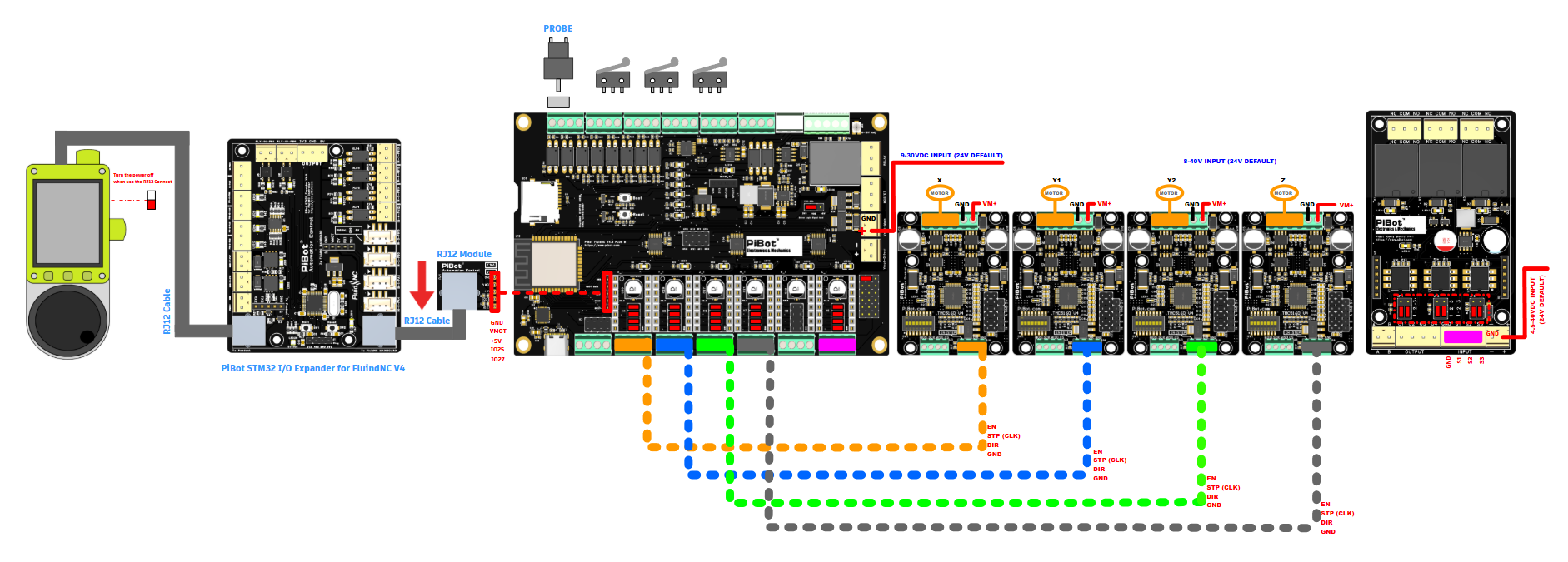
Tips: you can plug on the jumper for test in board without the main power connect, but if your use the main power please take this plug off.

Diagram of Driver Connection
Notice: en dir clk gnd model can not mix with the SPI model
Driver Connection Methods
A. Normal Stepstick STP/DIR DRIVER (such as A4988 Drv8825 TMC2208 TMC2209)
- Example YAML configurations:
- XYZABC Factory Test
- XYYZ Coolant
(1).png)
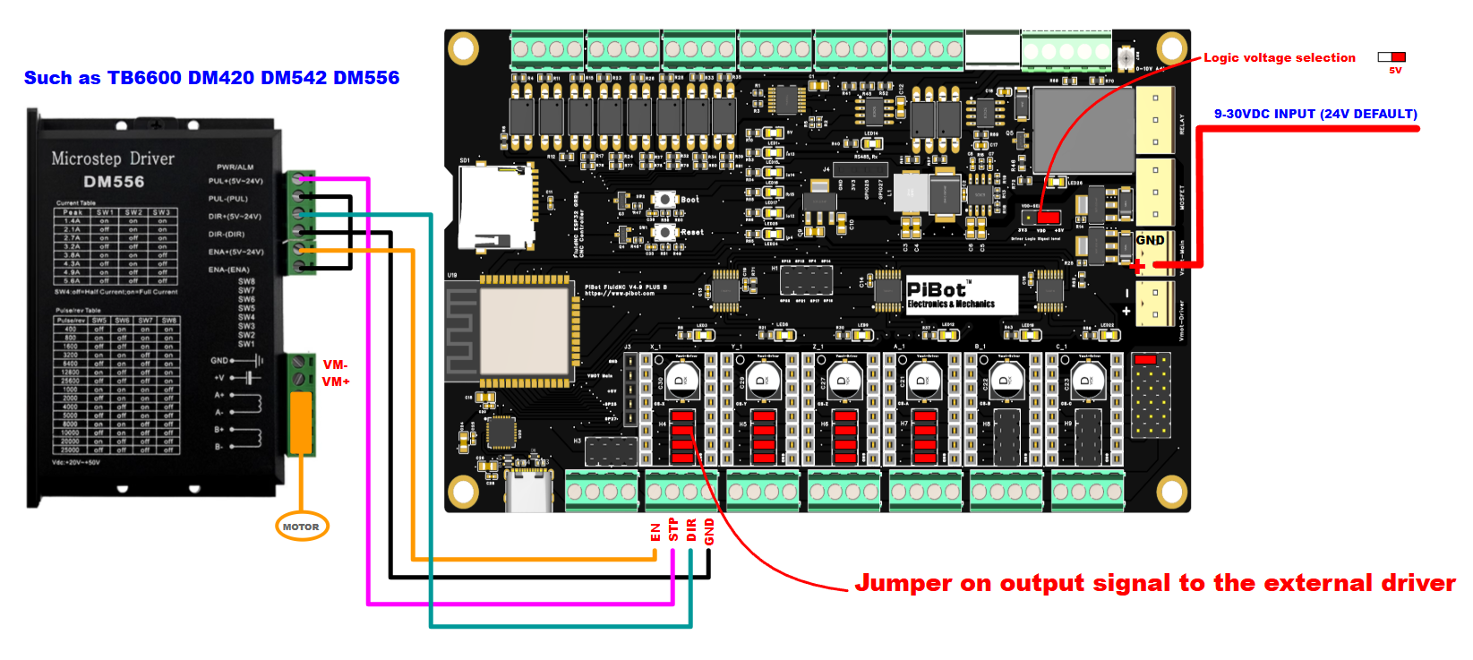
B. Normal Standard STP/DIR DRIVER (such as TB6600 DM420 DM542 DM556)
(1).png)
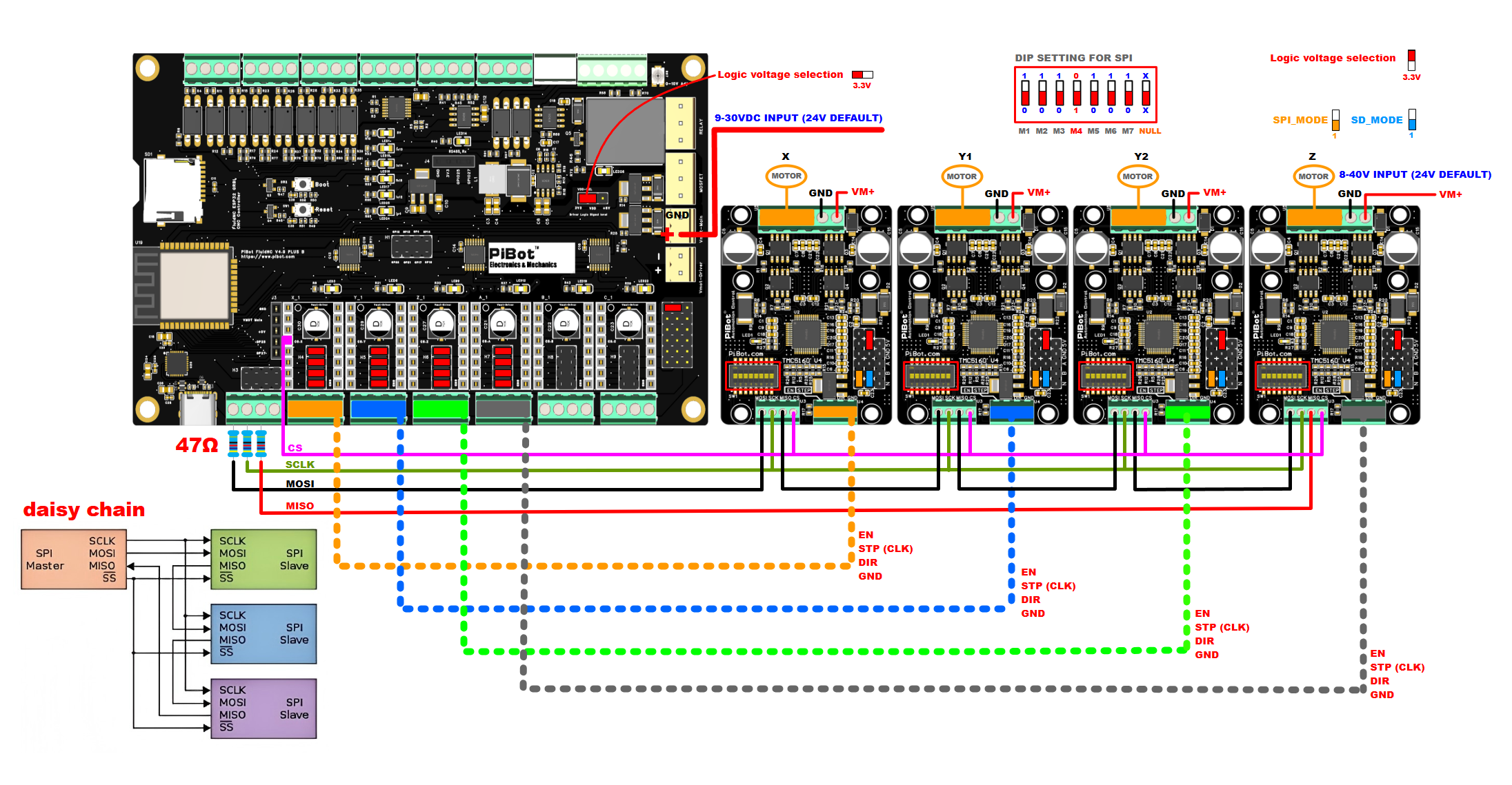
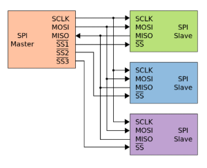
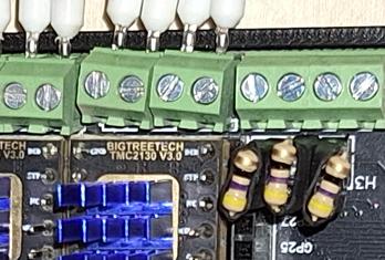
C. SPI TMC EXTERNAL DRIVER (such as TMC5160)
1. VDD set to 3.3V compatible with SPI voltage
2. Don't forget to use 47ohm resistor on mosi miso sck cable in V4.9 PB
- PiBot TMC5160 V4 page - Product Page
- Example YAML: TMC5160 Config (only for V49P-B)
- Test Video - Google Drive
D. SPI TMC ONBOARD DRIVER (such as TMC2130)
USE the independent mode each driver needs its own cs_pin
- Example YAML TMC2130 Config (only for V49P-B)
IMPORTANT NOTICES:
1. VDD set to 3.3V compatible with SPI voltage
2. It is important that when powering the board, Vmot-Driver is supplied first and then Vmot-main.
3. Don't forget to use 47ohm resistor on mosi miso sck cable in V4.9 PB
ONBOARD DRIVER PLUG BETWEEN THE JUMPERS
This feature tested by Alf from Italy.
Setup Guide (for FluidNC firmware)
Video Tutorials for Step 0 ~ Step 4
Notice:We have Uploaded and tested the Firmware and WebUI before Shipped, If you have OLED, it will display when plugged in.
The V4.9 plus and V4.8A V4.9A is similar config, different is the v4.9 plus step/dir model onboard driver "MS3 pin" need set in yaml.
Step 0: Preparation - Download Required Files
A. USB driver
B. ESP32 firmware
C. fluidnc web ui files: index.html and ico
D. YAML sample
Click here to download all at once:
If you need the latest software version, please download the latest release version from the fluidnc official website.
Step 1: Install USB Driver
(1) Insert the file A prepared earlier into your computer.
(2) If not installed correctly, install manually.
(3) Open "My Computer," go to Device Manager, and navigate to COM ports.
(4) Update the driver, select "Install from Local," and choose all.
(5) After installation, a CP2102 will be displayed, remember this port number.
Step 2: Upload FluidNC Firmware
(0) Connect via Type-C to your mainboard and power with 12V or 24V (theoretically, 9-30V is acceptable).
(1) Insert file B prepared earlier into your computer.
(2) Double click to open the WiFi version.
(3) If successful, it will install automatically; if not, press the boot button for three seconds and release to trigger automatic download.
(4) After download, select option 5.
(5) Disconnect power, wait for five seconds, then reconnect and restart the MCU.
- Latest Firmware: GitHub Releases
Step 3: Upload Web Interface Files
(1) After restarting the MCU, you'll find fluidnc in your computer's WiFi network.
(2) Connect to it with password 12345678.
(3) Once connected, enter 192.168.0.1 in your browser.
(4) Upload the required files, do not interrupt the process.
(6) After upload, you'll see the option to enter the web-fluidnc interface.
Step 4: Upload YAML Configuration
(1) Inside the interface, click here to proceed.
(2) Upload the YAML file you need for testing purposes. After testing, modify it according to your CNC requirements using this template.
(3) Click "Set" when done.
(3) Here, you can also configure your LAN access, refer to details.
(4) Disconnect power, wait for five seconds, then reconnect and restart the mainboard.
(6) The mainboard is now ready to work. If you have OLED, you can see basic information.
Example YAML Files:
Video Tutorials for Step5 (1)
Video Tutorials for Step5 (2~3)
Step 5: Hardware Testing Examples
(0) Mainboard pinout diagram.

(1) Relay // PWM // 0-10V output test example in default YAML configuration (use webUI test)

Testing Procedures:
A. Open the webUI page.
B. Click the unlock button.
C. Enter M6 to display the default tool, T0 as a relay.
D. Enter M6 T0 to test PWM.
E. Enter M6 T1 to test PWM.
F. Enter M6 T2 to test Laser.
G. Enter M6 T3 to test 0-10V.
H. Enter M6 T4 to test 485.
(2) Internal drive schematic (using the YAML provided as a sample)
A. Stepper motor drive pin jumper settings as shown in the diagram:
B. V4.9P NOW Only support "en dir clk gnd model", if you use TMC5160 please set to "en dir clk gnd" model,
C. V4.9PB support "en dir clk gnd model" and SPI model for TMC2130 OR TMC5160

YAML EXAMPLE:
stepstick:
    step_pin: I2SO.10
    direction_pin: I2SO.9
    disable_pin: I2SO.8
    ms3_pin: I2SO.11:high
(3) External drive schematic
A. It is recommended to use an independent power supply for external power.
B. Compatible with hardware REV2.3 REV4.0 relay.
C. Compatible with hardware REV2.3 TB6600 or DM420 driver etc.

.png)
YAML EXAMPLE:
standard_stepper:
    step_pin: I2SO.2
    direction_pin: I2SO.1
    disable_pin: I2SO.0:low
Additional Resources
Board Dimensions:
.png)
Schematic Diagrams:
V4.9PB Schematic (fixed SPI pin bugs from V4.9P):

V4.9P Schematic:

Antenna Information:
The v4.9PB has no onboard antenna, so it needs external antenna. If removed, WiFi signal may be lost.
Accessories:
- Electronic Box: 150×90×40mm Box
- OLED Display: 0.96" OLED
- Relay Board: Isolated Relay Board V4
- CNC Pendant: Pendant V4.0
- TMC5160 Driver: SilentStep TMC5160 V4
Shipping List
- PiBot FluidNC GRBL CNC Controller Board Rev4.9 Plus B × 1
- Jumpers Set x 1