Based on optical reflection principle, PiBot developed a non-contact platform automatic adjustment function to meet the needs of ± 2mm range of automatic adjustment.
Videos
The illustration of motion path
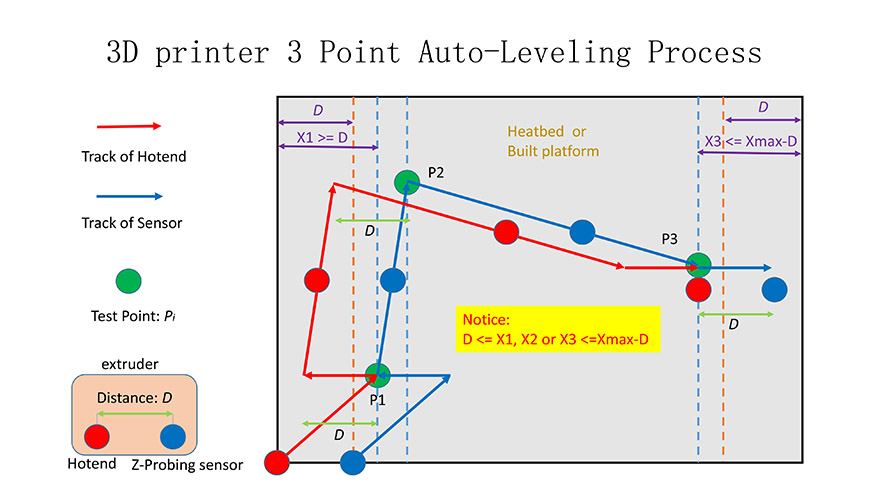
Step 1 : Confirm the Hardware
For Rev1.6
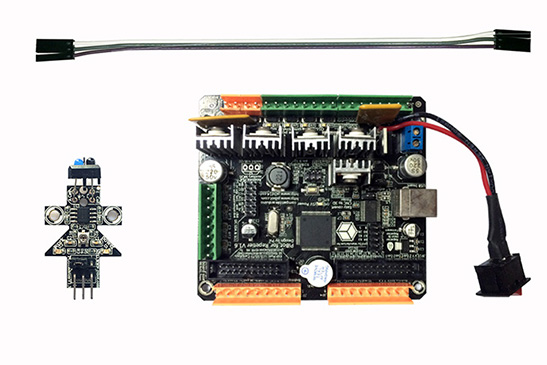
Step 2 : Connect and Test Electronics
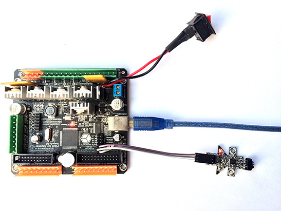
1. Hardware connection:
For Rev1.6
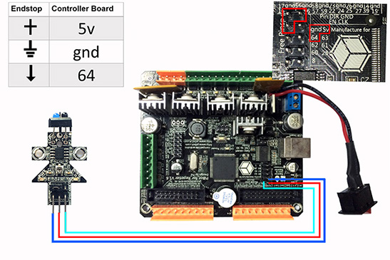
For Rev2.0
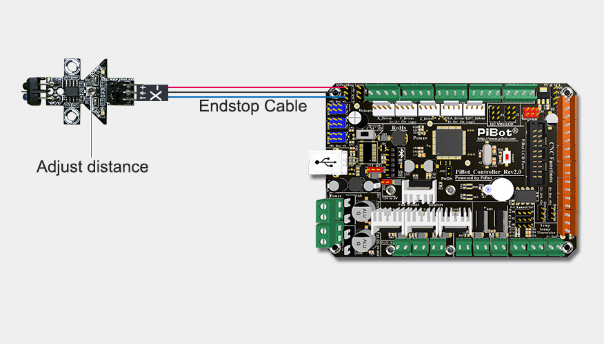
2.Electronics test:
Power in power source input port(12V-30V) or in USB port . Red LED light indicates power success.
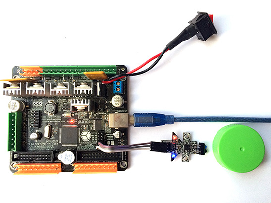
In the case of normal transmission of the signal,the blue LED will lights up when the distance of obstacle and probe near 15mm. In addition, the color of the obstacle can not be black.
3.The requirements of the sensor installation:
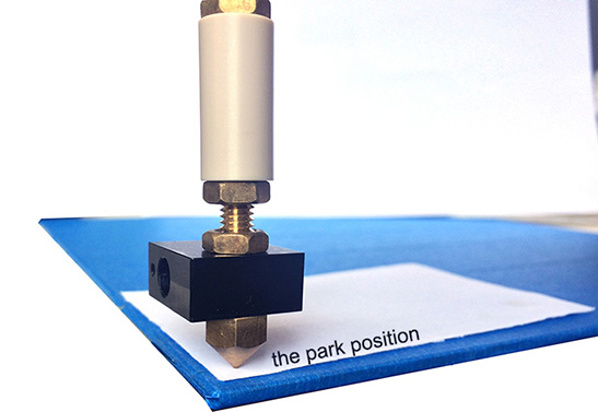
- Adjust the print platform to ensure the distance from the extrusion nozzle to work platforms in the park position is near the thickness of a sheet of paper in the parking position. And the extrusion nozzles will not touch the working platform at any point.
- The sensor is fixed to the vertical upper position of the printer nozzle and the distance from sensor probe to the extruder nozzle is near 10mm .
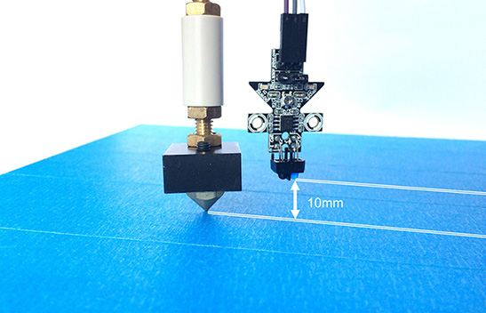
- Ensure the sensor probe remain at work within the platform range.
- The automatic adjustment range of the work platform is ± 2mm .
Now the hardware connection and installation is complete.
Step 3 : Download the Firmware and Upload Tools
PiBot 3D Printer Controller Board USB Driver Click Here for Download
The PiBot 3D Printer software have integrate the USB driver, if you have install the software,you don't need install the driver again.
PiBot 3D Printer Firmware Click Here for Download
Only need configure All parameter in one-page--”OnePageConfigure.h”.
Firmware Upload Tools Click Here for Download
Please use this version to upload your Firmware then you don't need to modifying anything.
Step 4 : Configure the Paremeter in "OnePageConfigure.h"
Now,unzip the files of firmware to a folder and find the file named OnePageConfigure,h.
Edit the parameters in this page which your just preparing above and save it. (Notepad++ recommended for editor tools)
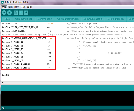
Set the following 6 parameters:Probing point1(near the park position),Probing point2,Probing point3,distance of senser and extruder in X axis,distance of senser and extruder in Y axis .
Make sure the probing points within your build platform , and near the edge.
Step 5 : Upload the Firmware to The Controller Board
1. Unzip the three files to separately floder.
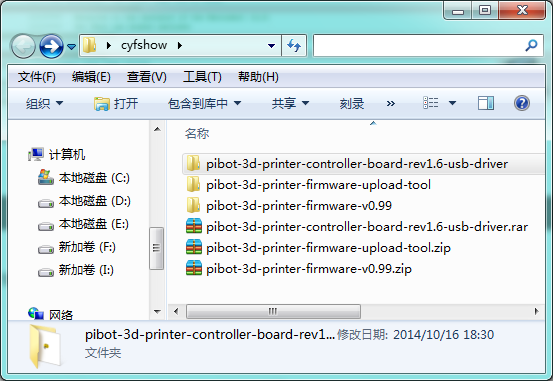
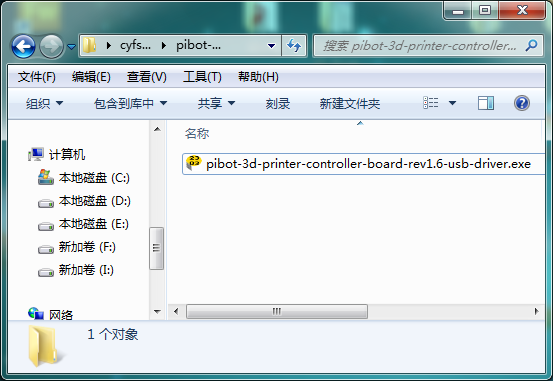
2. Install the  controller board USB driver then connect the controller board to the computer via USB wire
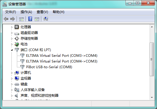
3. Check the COM number in Device Manager.
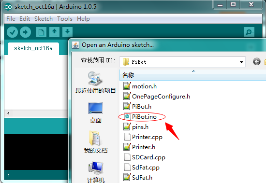
4. Run the  arduino.exe in the Upload tool folder and open the Pibot.ino which in the firmware folder.
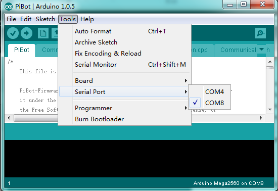
5. Select the COM which you check in Device Manager.
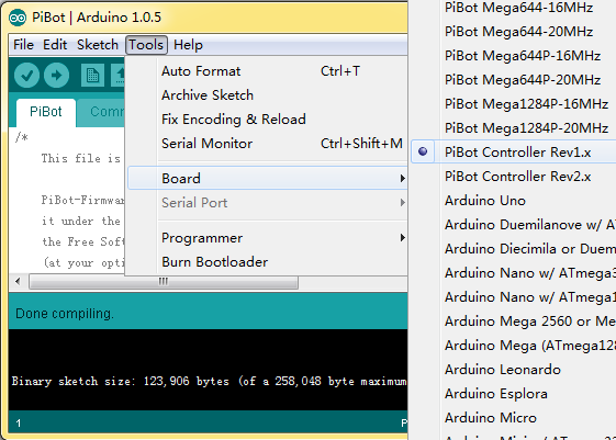
6. Select the board model - Aduino Mega 2560 in the arduino.exe
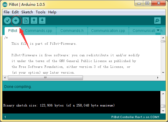
7. Verify and upload the firmware to the board
Step 6 :Open the PiBot 3D Printer Software
Select PI-Single-Extruder-Zprobe or PIHeatBed-Single-Extruder-Zprobe according to your requirements in the Printer Settings.
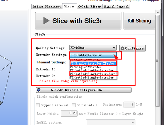
Slice with Slic3r
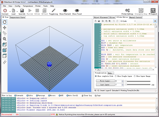
Import the code generated to your printer then the platform can achieve automatic adjustment function in the printing process.
