


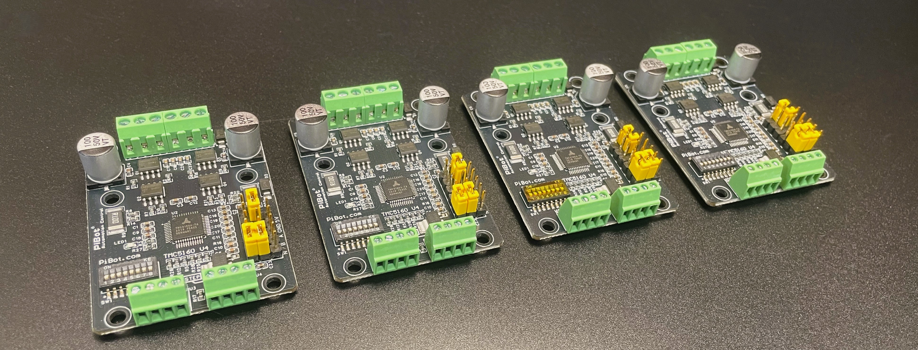
What is it
This product is specifically designed for broad compatibility with various CNC control boards, supporting not only our company's V4.7 and V4.9PB versions but also FluidNC 6X series. It supports standard stepper motor signals (en, dir, clk) and features an SPI communication interface. We have adopted a larger size and multi-layer PCB design to enhance heat dissipation and communication performance.
The product includes surge protection and is equipped with reverse power connection protection (though strict avoidance of reverse connection is still advised).
The TMC5160 excels in silent operation, delivering noticeable noise reduction when the silent function is enabled.
How it works
We have selected a 100 milliohm resistor as the sense resistor, so the maximum peak current is 3.3A, with an operating voltage range of 8-40V (we recommend using 24V for testing). If you require a higher current, you will need to replace the sense resistor and solder it in. As for the corresponding sense resistor values and the achievable current levels, please refer to the TMC5160 datasheet. Achieving higher currents requires consideration of the PCB structure and heat dissipation, but doing so will void our support and warranty.
This driver board can support stepper motors such as Nema17 and Nema23 series.
Overview

1. Logic Voltage Selection
The logic level can be set via a jumper cap, with options for 3.3V and 5V, to accommodate various external controllers such as 3.3V microcontrollers, 5V microcontrollers, and 5V PLC systems.
2. Mode Selection
The TMC5160 has four operating modes, which can be selected by configuring the SD_Mode and SPI_Mode pins using jumper caps. By setting the logic levels of these two pins, users can switch freely among the four modes (note: mode switching should be performed after power-off).
Mode Selection Table:
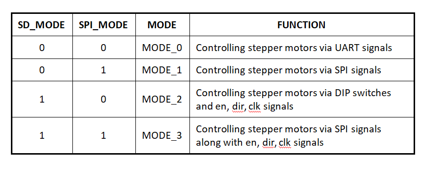
Mode 0: UART Mode (This mode is not used by PiBot's mainboard. If this functionality is required, users need to consult the manual themselves.)
Mode 1: In this mode, parameters such as microstepping, current, silent operation, and half-current can be configured via the SPI interface by setting the corresponding registers. After configuring these parameters, the motor can start moving by setting the initial speed, maximum speed, acceleration, deceleration, target position, and other information via the SPI interface. This mode does not require external pulse or direction input.
Mode 2: Standard Mode (Ordinary Mode): This mode does not require parameter configuration via the SPI interface. In this mode, the current and microstepping settings are configured using DIP switches. The motor can be controlled simply by providing pulse, direction, and enable signals from an external controller.
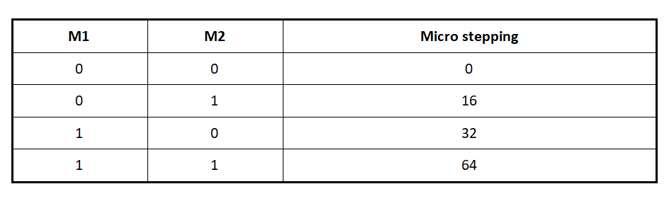
Microstepping Settings
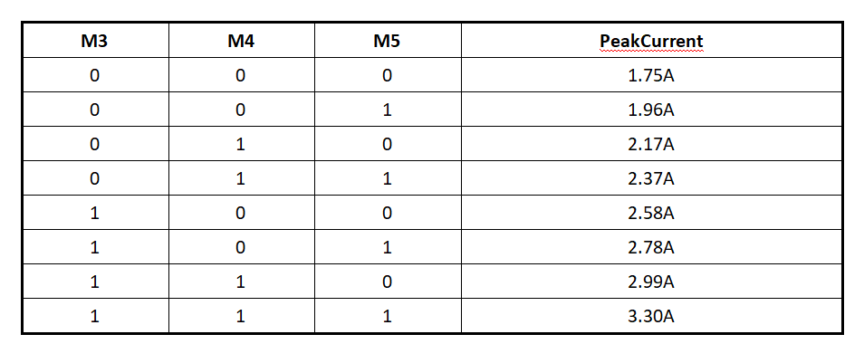
Chopper Mode Settings

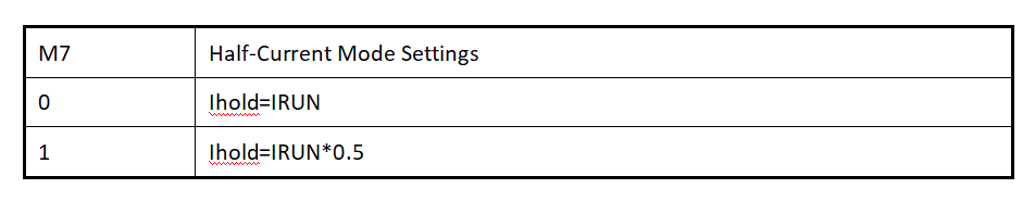
Half-Current Mode Settings
Since the current settings are not continuous, it is possible that the minimum current or certain step currents may exceed the rated current of your motor, leading to overheating. Therefore, it is essential to select an appropriate motor.
Typical Connection A: (Mode 2 - Standard Mode) Connect to V4.7 or V4.9PB, etc. (compatible with most standard mainboards). Please note that the positions of M4 switch settings 0 and 1 differ from others.
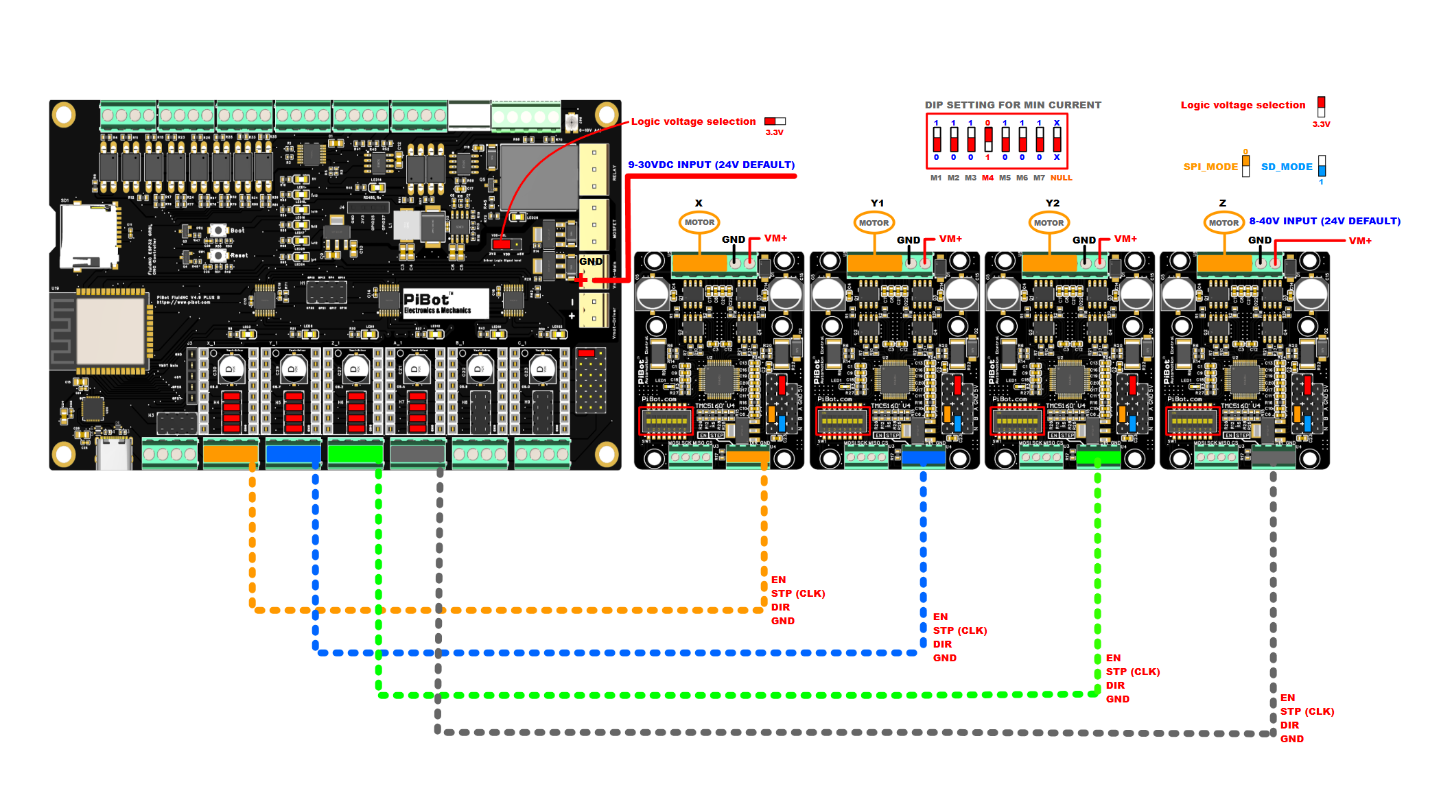
YAML Code Example:
standard_stepper:
  step_pin: I2SO.2
  direction_pin: I2SO.1
  disable_pin: I2SO.0
Mode 3: This mode requires not only configuring parameters such as microstepping, current, silent operation, and half-current via the SPI interface by setting the corresponding registers but also relies on external controller inputs for pulse, direction, and enable signals to control the motor.
(The DIP switches must be set to the default state as shown in the figure: 0001000. Otherwise, the SPI pin logic levels may be affected.)
This connection method is compatible with the V4.9PB mainboard, allowing parameters like current to be configured in the YAML file and transmitted to the TMC5160 via SPI signals.
Typical Connection B: (Mode 3 - SPI Mode) Connect to V4.9PB
1. On the V4.9PB, select 3.3V logic voltage and set the SPI output mode jumper. Configure the port to pulse-direction signal output mode.
2. Set the driver port to 3.3V logic voltage. Configure SPI_Mode=1 and SD_Mode=1 (i.e., Mode 3) and select the corresponding DIP switch settings.
3. For daisy chain SPI mode output, a 47-ohm resistor must be connected.
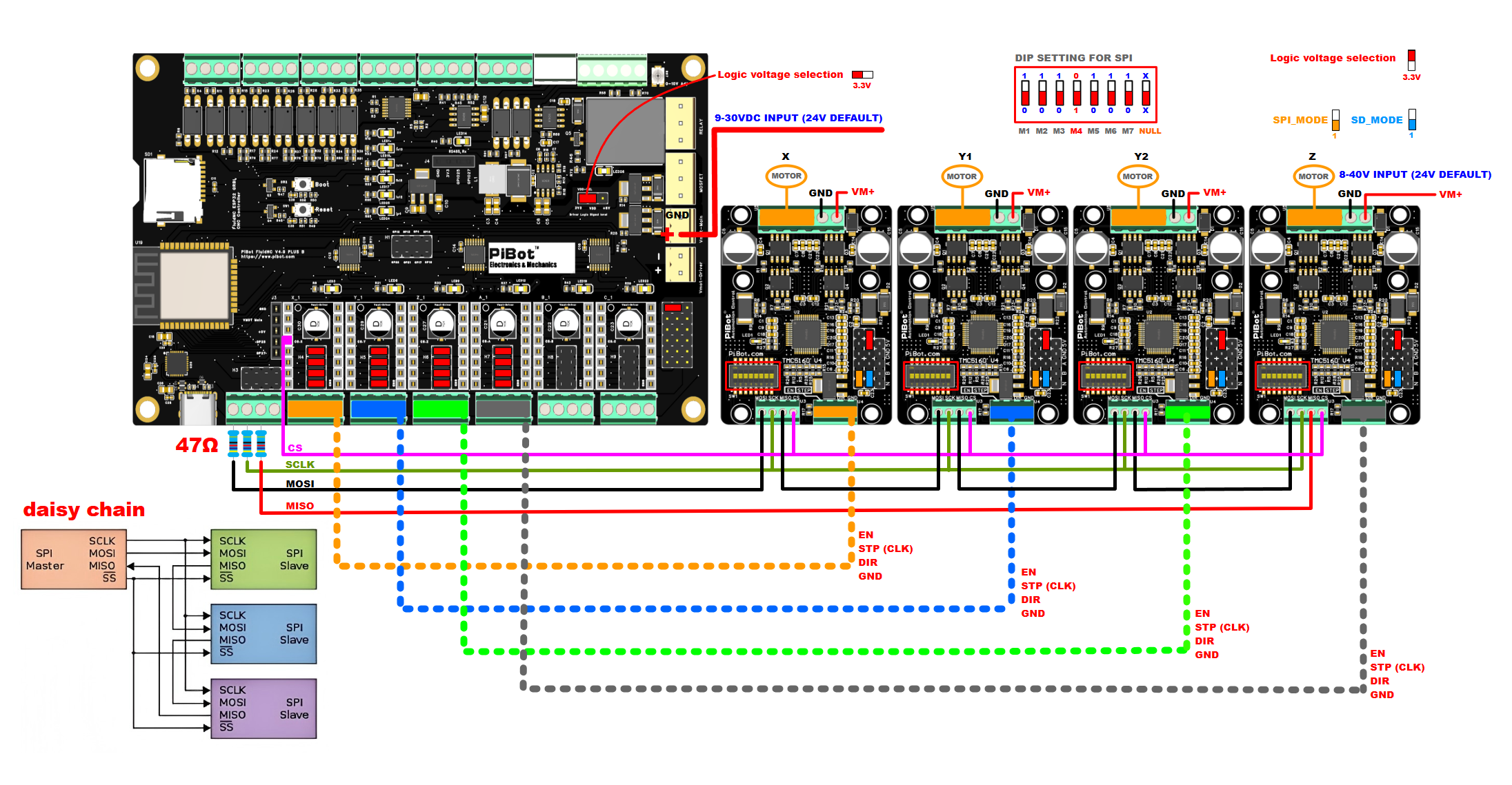
YAML Code Example:
      tmc_5160:
        r_sense_ohms: 0.1
        run_amps: 0.5
        hold_amps: 0.1
        microsteps: 16
        stallguard: 0
        stallguard_debug: false
        toff_disable: 0
        toff_stealthchop: 5
        toff_coolstep: 3
        run_mode: CoolStep
        homing_mode: CoolStep
        use_enable: false
        cs_pin: i2so.3
        step_pin: I2SO.2
        direction_pin: I2SO.1
        disable_pin: I2SO.0
        spi_index: 1
YAML file: https://www.pibot.com/dls/tmc5160v4/yaml-config-tmc5160-V1.zip
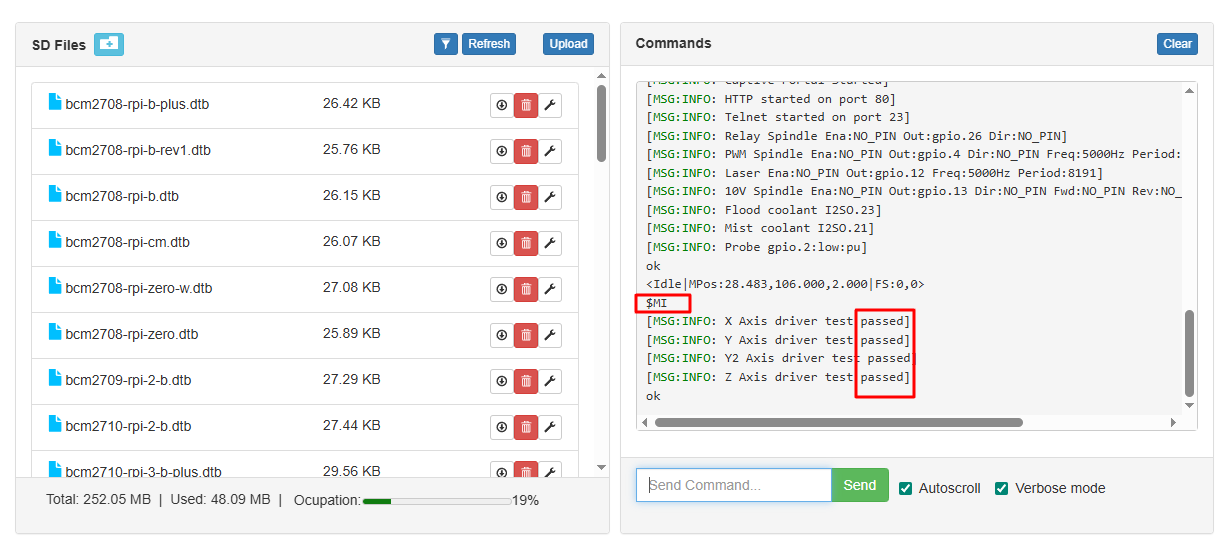
Test Command: $MI
4. Other Features:
Encoder Interface: The TMC5160 supports ABN encoder input. Traditionally, encoder signals are returned to the controller. However, the TMC5160's capability allows encoder signals to be directly fed back to the TMC5160 to achieve closed-loop control. For details, refer to the TMC5160 manual.
DIG Output: For specific information, please refer to the TMC5160 manual.
5. Notes:
Regardless of the mode used, the enable pin (EN) must be controlled. The motor will only move when EN is set to a low level. Additionally, a common ground connection is required—the GND pin must be connected to the controller's GND.
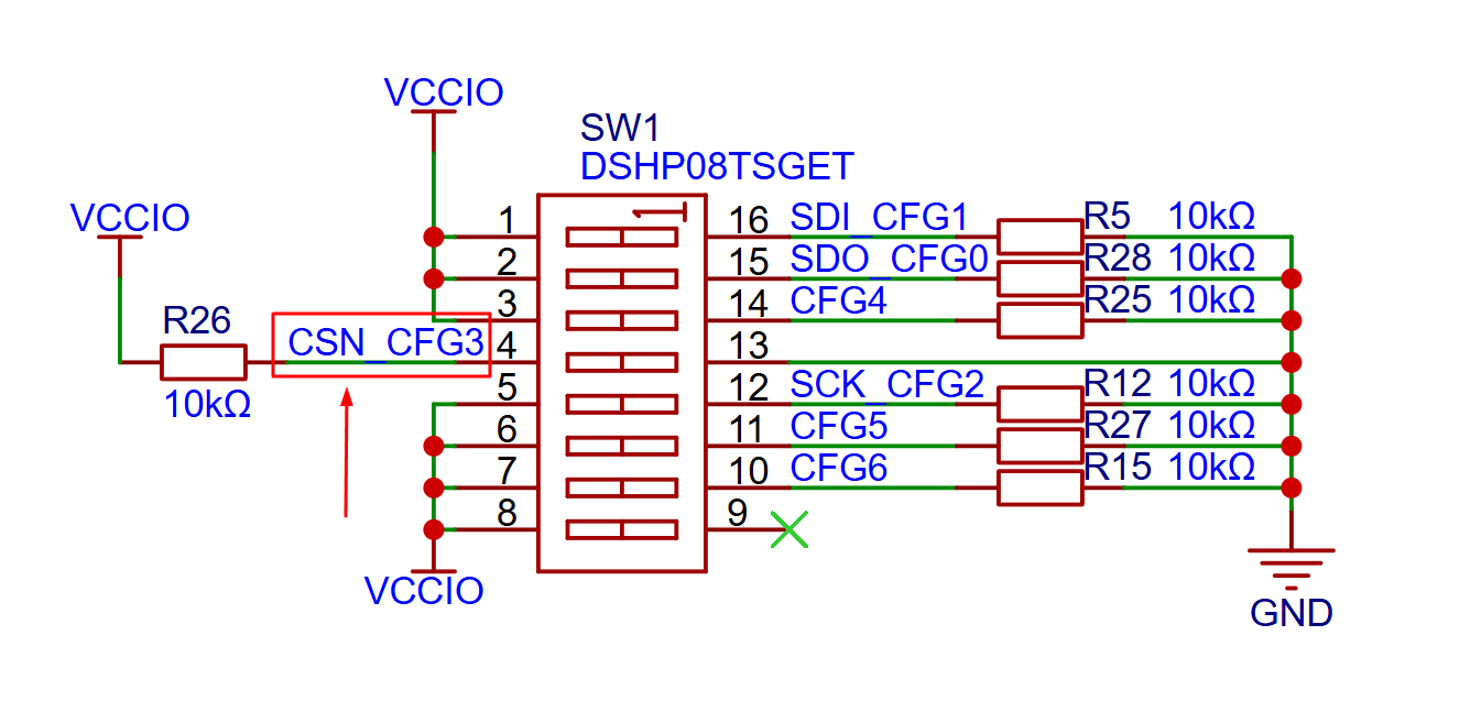
(Please note: Due to the pull-up resistor implemented in our CFG3-CSN, switching downward corresponds to a high level, while switching upward corresponds to a low level (GND). For all other configurations, downward switching indicates a low level, and upward switching indicates a high level. Why this design? Because some outputs lack pull-up resistors, we have added pull-up resistors to the CS and EN pins on the TMC5160 board.)
Main Parameters
- Chip: TMC5160
- Voltage: 8-40VDC
- Current: 3.3A
- Sense Resistor: 0.1 Ohm
- Logic Voltage: 3.3V or 5V
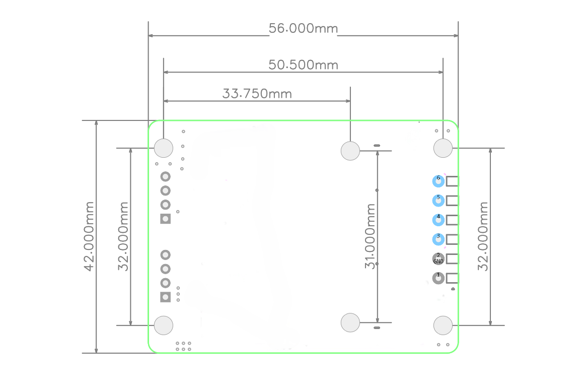
- Dimensions: 42mm * 56mm
- Mounting Hole Size: 3mm
- Heat Sink Size: 30*20*10mm
Dimensions
Documentation
- Schematic Diagram https://www.pibot.com/dls/tmc5160v4/Schematic-tmc5160-pibot.pdf
- TMC5160 Driver Manual (English) https://www.pibot.com/dls/tmc5160v4/TMC516-english-guider.pdf
Package Contents
- Driver × 1
- Heat Sink × 1
- Jumper Cap Pack × 1

-250x250.jpg "DRV8825 Stepper Motor Driver")


%20(1)-250x250h.png "IPEX to SMA external antenna")
-250x250w.png "IPEX to SMA external antenna")

")
")


-250x250.jpg "TMC2208 Stepper Motor Driver")
-550x550-250x250.jpg "TMC2225 Stepper Motor Driver")

-550x550-250x250.png "A4988 Stepper Motor Driver")

")